Transform Orientations
Reference
Alt-SpacebarOrientations affect the behavior of Transformations: Location, Rotation, and Scale.
You will see an effect on the 3D Manipulator (the widget in the center of the selection),
as well as on transformation constraints
(like axis locking).
This means that, when you press G-X, it will constrain to the global X-axis,
but if you press G-X-X it will constrain to your Transform Orientation s X-axis.
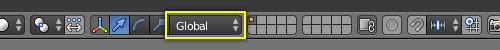
Transform Orientations selector.
The Orientations options can be set through the Orientation selector in a 3D View header,
with Alt-Spacebar, or in the Transform Orientations panel in the Properties region.
- Transform Orientations
- In addition to the four preset options, you can define your own custom orientation (see Custom Orientations below).
Orientations
- Global
The manipulator matches the global axis.
When using the Global orientation, the orientation’s XYZ matches world’s XYZ axis. When this mode is selected, the local coordinates of the object are subjected to the Global coordinates. This is good to place objects in the scene. To constrain an axis, press
Gand the desired axis. To constrain to a local axis, press the desired axis two times. The difference between Global and Local, is more noticeable when you have an object in which the origin is not located at the exact center of the object, and does not match the Global coordinates.- Local
The manipulator matches the object axis.
Notice that, here, the Manipulator is at a slight tilt (it is most visible on the object’s Y-axis, the green arrow). This is due to our 15° rotation of the object. This demonstrates the difference between local coordinates and global coordinates. If we had rotated the object 90° along its X-axis, we would see that the object’s “Up” is the world’s “Forward” – or the object’s Z-axis would now be the world’s Y-axis. This orientation has an effect on many parts of the interface, so it is important to understand the distinction.
- Normal
The Z-axis of the manipulator will match the normal vector of the selection.
In Object Mode, this is equivalent to Local Orientation, in Edit Mode, it becomes more interesting.
As you see, the light blue lines indicate the faces’ normals, and the darker blue lines indicate the vertex normals (these were turned on in the
NProperties region under and Vertex). Selecting any given face will cause our Manipulator’s Z-axis to align with that normal. The same goes for Vertex Select Mode. Edge Select is different – A selected Edge has the Z-axis aligned with it (so you will have to look at the Manipulator widget to determine the direction of X and Y). If you select several elements, it will orient towards the average of those normals.A great example of how this is useful is in Vertex Select Mode: Pick a vertex and then do
G, Z, Zto tug it away from the mesh and shove it into the mesh. To make this even more useful, select a nearby vertex and pressShift-Rto repeat the same movement – except along that second vertex’s normal instead.- Gimbal
- Uses a Gimbal behavior that can be changed depending on the current Rotation Mode.
- View
The manipulator will match the 3D View:
- Y: Up/Down
- X: Left/Right
- Z: Towards/Away from the screen.
This way you can constrain movement to one View axis with
G-X-X.
Custom Orientations
Reference
Ctrl-Alt-Spacebar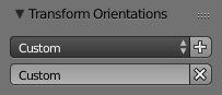
Custom orientation.
You can define custom transform orientations, using object or mesh elements. Custom transform orientations defined from objects use the local orientation of the object whereas those defined from selected mesh elements (vertices, edges, faces) use the normal orientation of the selection.
The Transform Orientations panel, found in the Properties region, can be used to manage transform orientations: selecting the active orientation, adding and deleting custom orientations.
Renaming a Custom Orientation.
The default name for these orientations comes from whatever you have selected. If an edge, it will be titled, “Edge,” if an object, it will take that object’s name, etc.
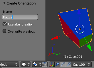
Create Orientation
Just after creating the orientation, the Create Orientation Operator panel gives a few options:
- Name
- Text field for naming the new orientation.
- Use View
- The new orientation will be aligned to the view space.
- Use after creation
- If checked it leaves the newly created orientation active.
- Overwrite previous
- If the new orientation is given an existing name, a suffix will be added to it to avoid overwriting the old one, unless Overwrite previous is checked, in which case it will be overwritten.
Workflow
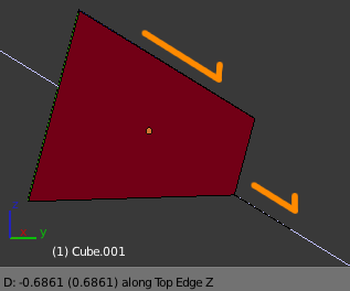
Custom Extrusion.
The technique of creating custom orientations can become important in creating precise meshes. In Fig. Custom Extrusion., to achieve this effect:
- Select the object’s sloping top edge
- Create a Custom Orientation with
Ctrl-Alt-Spacebarand rename it “Top Edge”. - Select the objects’s bottom, right edge.
- Extrude with
E. - Cancel the extrusion’s default movement by pressing
RMBorEsc. - Hit
Gto reinitiate movement. - Hit
Z-Zto constrain to the “Top Edge” orientation.
Align to Transform Orientation
Reference
Aligns (rotates) the selected objects so that their local orientation matches the active transform orientation in the Transform orientation panel or the Orientation selection in the Transform Operator panels.
Examples
Demo Cube
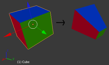
To demonstrate the various behaviors, we add some colors to the default cube, rotate it -15° along its local Z- and X Axes, and we scale its “y” face down.
Please note two things:
- The “Mini-axis” in the lower-left corner, which represents the Global X, Y, Z orientation.
- The “Object Manipulator”
widget emanating from the selection, which represents the current Transform Orientation.
- If you click on one of the axes of the Manipulator with
LMB, it will allow you to constrain movement to only this direction. An example of a keyboard equivalent isG, Z, Z. - If you
Shift-LMBclick, it will lock the axis you clicked on and allow you to move in the plane of the two remaining axes. The keyboard analogue isG, Shift-Z, Shift-Z.
- If you click on one of the axes of the Manipulator with
Effect on Manipulators
The image below shows a cube with the rotation manipulator active in multiple transform orientations. Notice how the manipulator changes depending on the orientation selected (compare A with F).
Similarly, notice how when normal orientation (F and G) is selected the manipulator changes between Object Mode and Edit Mode. The normal orientation manipulator will also change depending on what is selected in Edit Mode i.e. the orientation is based on the normal of the selection which will change depending on how many and which faces, edges or vertices are selected.
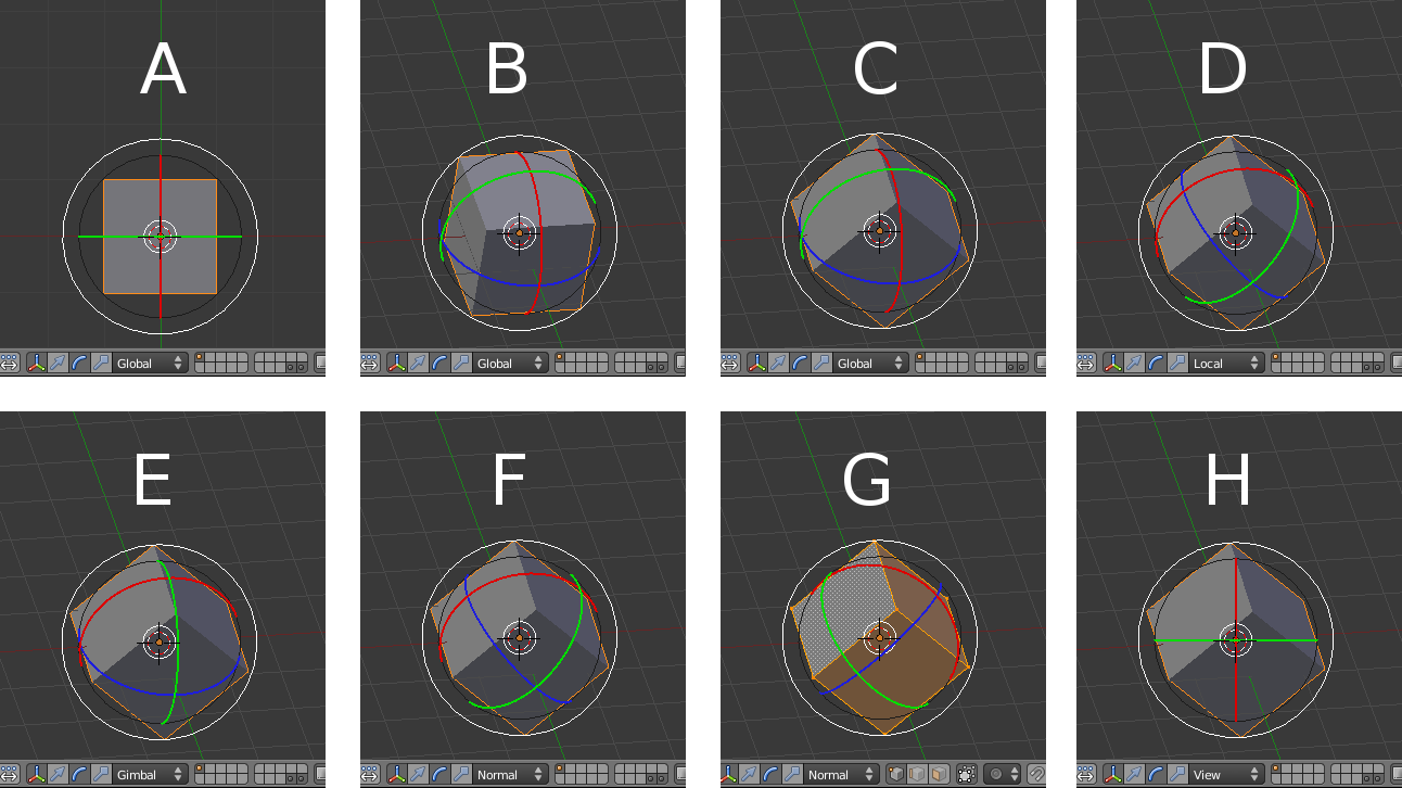
Transform manipulator orientation options.
- Standard cube in default top view with global orientation selected
- Standard cube with view rotated and global orientation selected
- Randomly rotated cube with view rotated and global orientation selected
- Randomly rotated cube with local orientation selected
- Randomly rotated cube with gimbal orientation selected
- Randomly rotated cube with normal orientation selected
- Randomly rotated cube, vertices selected with normal orientation selected
- Randomly rotated cube with view orientation selected