Editing
Surface editing has even fewer tools and options than its curve counterpart, but has many common points with it... So this page covers (or tries to cover) all the subjects, from the basics of surface editing to more advanced topics, like retopology.
Translation, Rotation, Scale
Reference
G, R, SOnce you have a selection of one or more control points,
you can grab/move G, rotate R or scale S them, like many other things in Blender,
as described in the Manipulation in 3D Space section.
You also have in Edit Mode an extra option when using these basic manipulations: the proportional editing.
Transform Panel
See Transform Panel.
Advanced Transform Tools
Reference
The To Sphere, Shear, Warp and Push/Pull transform tools are described in the Mesh Transformation section. Surfaces have no specific transform tools.
NURBS Control Points Settings
Reference
We saw in a previous page that NURBS control points have a weight, which is the influence of this point on the surface. You set it either using the big Set Weight button in the Curve Tools panel (after having defined the weight in the number button to the right), or by directly typing a value in the W number button of the Transform panel.
Adding or Extruding
Reference
E, Ctrl-LMBUnlike meshes or curves, you cannot generally directly add new control points to a surface
(with Ctrl-LMB clicks), as you can only extend a surface by adding a whole U- or V-row at once.
The only exception is when working on a NURBS surface curve, i.e.
a surface with only one control point on each U- or V-row. In this special case,
all works exactly as with curves.
Most of the time, only extrusion is available. As usual, once the tool is activated the extrusion happens immediately and you are placed into Grab mode, ready to drag the new extruded surface to its destination.
There are two things very important to understand:
- Surfaces are 2D objects. So you cannot extrude anything inside a surface (e.g. “inner” row); it would not make any sense!
- The control “grid” must remain “squarish”, which means that you can only extrude a whole row, not parts of rows here and there...
To summarize, the Extrude tool will only work, when one and only one whole border row is selected, otherwise nothing happens.
As for curves, you cannot create a new surface in your object out of nowhere,
by just Ctrl-LMB - clicking with nothing selected.
However, unlike for curves, there is no “cut” option allowing you to separate a surface into several parts,
so you only can create a new surface by copying (Duplication) an existing one
Shift-D, or adding a new one with the Add menu.
Examples
Images Fig. Selecting control-point. to Fig. Extruding. show a typical extrusion along the side of a surface.
In Fig. Selecting control-point. and Shift-R,
a border row of control points were highlighted by selecting a single control point,
and then using the handy row select tool Shift-R
to select the rest of the control points.
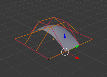
Selecting control-point. |
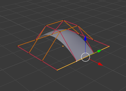
Shift-R |
The edge is then extruded using E as shown in Fig. Extruding..
Notice how the mesh has bunched up next to the highlighted edge.
That is because the new extruded surface section is bunched up there as well.
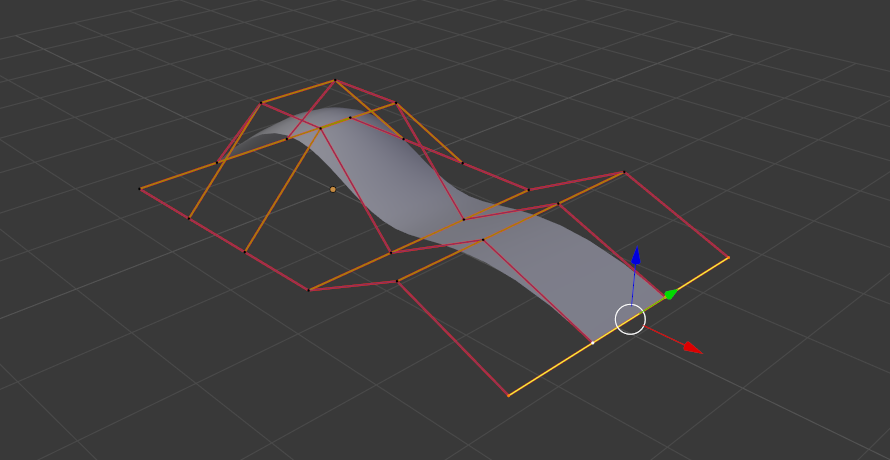
Extruding.
By moving the new section away from the area, the surface begins to “unbunch”.
You can continue this process of extruding or adding new surface sections until you have reached the final shape for your model.
Opening or Closing a Surface
Reference
Alt-CAs in curves, surfaces can be closed (cyclic) or open. However, as surfaces are 2D, you can control this property independently along the U and V axes.
To toggle the cyclic property of a surface along one axis,
use Alt-C and choose either cyclic U or cyclic V from the pop-up menu.
The corresponding surface’s outer edges will join together to form a “closed” surface.
Note
Inner and Outer
Surfaces have an “inner” and “outer” face, the first being black whereas the latter is correctly shaded. (There does not seem to be any “double sided” shading option for surfaces...). When you close a surface in one or two directions, you might get an entirely black object! In this case, just Switch Direction of your surface...
Duplication
Reference
Shift-DSimilar as with meshes and curves, this tool duplicates the selection. The copy is selected and placed in Grab mode, so you can move it to another place.
However, with surfaces there are some selections that cannot be duplicated, in which case they will just be placed in Grab mode... In fact, only selections forming a single valid sub-grid are copyable; let us see this in practice:
- You can copy a single control point. From it, you will be able to “extrude” a “surface curve” along the U axis, and then extrude this unique U-row along the V axis to create a real new surface.
- You can copy a single continuous part of a row (or a whole row, of course). This will give you a new U-row, even if you selected (part of) a V-row!
- You can copy a single whole sub-grid.
Note
Trying to duplicate several valid “sub-grids” (even being single points) at once will not work; you will have to do it one after the other...
Deleting Elements
Reference
X, DeleteThe Erase pop-up menu of surfaces offers you two options:
- Selected
This will delete the selected rows, without breaking the surface (i.e. the adjacent rows will be directly linked, joined, once the intermediary ones are deleted). The selection must abide by the following rules:
- Whole rows, and only whole rows must be selected.
- Only rows along the same axis must be selected (i.e. you cannot delete both U- and V-rows at the same time).
Also remember that NURBS order cannot be higher than its number of control points in a given axis, so it might decrease when you delete some control points... Of course, when only one row remains, the surface becomes a “surface curve”; when only one point remains, there is no more visible surface; and when all points are deleted, the surface itself is deleted.
- All
- As with meshes or curves, this deletes everything in the object!
Example
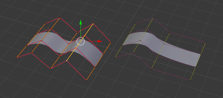
Before and after.
In Fig. Before and after (left) a row of control points has been selected by initially
selecting the one control point and using Shift-R to select the remaining
control points. Then, using the Delete Menu X,
the selected row of control points is erased, resulting in Fig. Before and after (right).
Joining or Merging Surfaces
Reference
FJust like curves,
merging two surfaces requires that a single edge, a border row of control points,
from two separate surfaces are selected. This means that the surfaces must be part of the same object. For example,
you cannot join two surfaces while in Object Mode - but you can of course, as with any objects of the same type,
join two or more Surface objects
into one object Ctrl-J - they just will not be “linked” or merged in a single one... Yes, it’s a bit confusing!
This tool is equivalent to creating edges or faces for meshes
(hence its shortcut), and so it only works in Edit Mode.
The selection must contains only border rows of the same resolution
(with the same number of control points),
else Blender will try to do its best to guess what to merge with what, or the merge will fail
(either silently, or stating that Resolution does not match if rows with
different number of points are selected, or that there is Too few selections to merge
if you only selected points in one surface...).
To select control points of different surfaces,
in the same object, you must use either border select or circle select.
Holding down Ctrl while LMB will not work.
So to avoid problems, you should always only select border rows with the same number of points... Note that you can join a border U-row of one surface with a border V-row of another one, Blender will automatically “invert” the axis of one surface for them to match correctly.
NURBS surface curves are often used to create objects like hulls, as they define cross sections all along the object, and you just have to “skin” them as described above to get a nice, smooth and harmonious shape.
Examples
Fig. Joining ready is an example of two NURBS surface curves, not NURBS curves, in Edit Mode, ready to be joined. Fig. Joining complete is the result of joining the two curves.
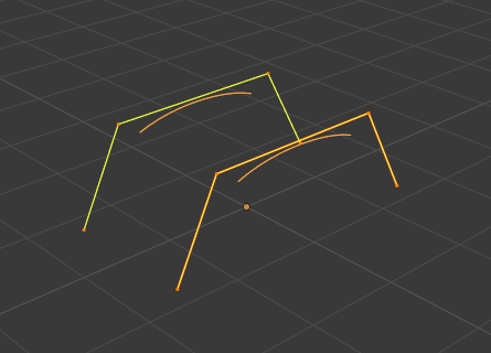
Joining ready. |
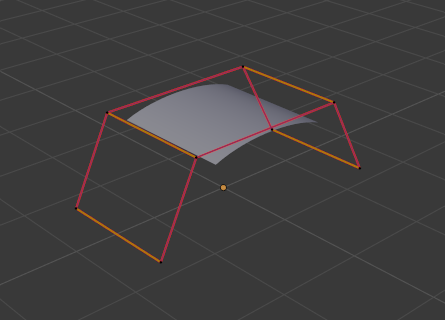
Joining complete. |
Subdivision
Reference
Surface subdivision is most simple:
using either the Subdivide entry in the Specials menu
W, or the Subdivide button of the Curve Tools1 panel,
you will subdivide once all completely selected grids by subdividing each “quad” into four
smaller ones.
If you apply it to a 1D surface (a “surface curve”), this tool works exactly as with curves.
Spin
Reference
This tool is a bit similar to its mesh counterpart but with less control and options (in fact, there is none!).
It only works on selected “surfaces” made of one U-row (and not with one V-row), so-called “surface curves”, by “extruding” this “cross section” in a square pattern, automatically adjusting the weights of control points to get a perfect circular extrusion (this also implies closing the surface along the V axis), following exactly the same principle as for the NURBS Tube or NURBS Donut primitives.
Switch Direction
Reference
This tool will “reverse” the direction of any curve with at least one selected element (i.e. the start point will become the end one, and vice versa). Mainly useful when using a curve as path, or the bevel and taper options...
Other Specials Options
Reference
WThe Specials menu contains exactly the same additional options as for curves, except for Set Radius and Smooth Radius.
Conversion
As there are only NURBS surfaces, there is no “internal” conversion here.
However, there is an “external” conversion available, from surface to mesh, that only works in Object Mode. It transforms a Surface object into a Mesh one, using the surface resolutions in both directions to create faces, edges and vertices.
Misc Editing
You have some of the same options as with meshes, or in Object Mode.
You can separate a given surface P,
make other selected objects children
of one or three control points
Ctrl-P,
or add hooks to control some points with other objects.
The Mirror tool is also available, behaving exactly as with mesh objects.