Mapping Types
Reference
Ctrl-UBlender offers several ways of mapping UVs. The simpler projection methods use formulas that map 3D space onto 2D space, by interpolating the position of points toward a point/axis/plane through a surface. The more advanced methods can be used with more complex models, and have more specific uses.
Basic:
- Cube Projection
- Maps the mesh onto the faces of a cube, which is then unfolded.
- Sphere
- Projects the UVs onto a spherical shape. Useful only for spheres or spherical shapes, like eyes, planets, etc.
- Cylinder
- Projects UVs onto a cylindrical surface.
- Project from View
- Takes the current view in the 3D View and flattens it as it appears.
Advanced:
- Unwrap
- Useful for organic shapes. Smooths the mesh into a flat surface by cutting along seams.
- Smart UV Project
- Breaks the mesh into islands based on an angle threshold.
- Lightmap Pack
- Separates each face and packs them onto the UV grid.
- Follow Active Quads
- Follow UV from active quads along continuous face loops.
You can also Reset UVs, which maps each face to fill the UV grid, giving each face the same mapping.
If we were to use an image that was tileable, the surface would be covered in a smooth repetition of that image, with the image skewed to fit the shape of each individual face. Use this unwrapping option to reset the map and undo any unwrapping (go back to the start).
Unwrap
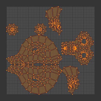
Result of unwrapping Suzanne.
Begin by selecting all faces to be unwrapped in the 3D View. With our faces selected,
it is now time to unwrap them.
In the 3D View, select or
U and select Unwrap.
You can also do this from the UV/Image Editor with or E.
This method will unwrap all of the faces and reset previous work. The
UVs menu will appear in the UV/Image Editor after unwrapping has been performed once.
This tool unwraps the faces of the object to provide the “best fit” scenario based on how the faces are connected and will fit within the image, and takes into account any seams within the selected faces. If possible, each selected face gets its own different area of the image and is not overlapping any other faces UV’s. If all faces of an object are selected, then each face is mapped to some portion of the image.
Operator panel
Blender has two ways of calculating the unwrapping. They can be selected in the tool setting in the tool panel in the 3D View.
- Angle Based
- This method gives a good 2D representation of a mesh.
- Conformal
- Uses LSCM (Least Squared Conformal Mapping). This usually gives a less accurate UV mapping than Angle Based, but works better for simpler objects.
- Fill Holes
- Activating Fill Holes will prevent overlapping from occurring and better represent any holes in the UV regions.
- Correct Aspect
- Map UVs taking image aspect into account.
- Use Subdivision Surface Modifier
- Map UVs taking vertex position after Subdivision Surface Modifier into account.
- Margin
- Space between UV islands.
Tip
A face’s UV image texture only has to use part of the image, not the whole image. Also, portions of the same image can be shared by multiple faces. A face can be mapped to less and less of the total image.
Smart UV Project
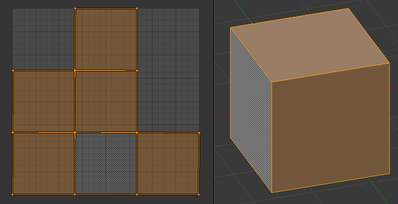
Smart UV project on a cube.
Smart UV Project, (previously called the Archimapper) gives you fine control over how automatic seams should be created, based on angular changes in your mesh. This method is good for simple and complex geometric forms, such as mechanical objects or architecture.
This function examines the shape of your object, the faces selected and their relation to one another, and creates a UV map based on this information and settings that you supply.
In the example to the right, the Smart Mapper mapped all of the faces of a cube to a neat arrangement of three sides on top, 3 sides on the bottom, for all six sides of the cube to fit squarely, just like the faces of the cube.
For more complex mechanical objects, this tool can very quickly and easily create a very logical and straightforward UV layout for you.
Operator panel
The Operator panel in the Tool Shelf allows the fine control over how the mesh is unwrapped:
- Angle Limit
- This controls how faces are grouped: a higher limit will lead to many small groups but less distortion, while a lower limit will create fewer groups at the expense of more distortion.
- Island Margin
- This controls how closely the UV islands are packed together. A higher number will add more space in between islands.
- Area Weight
- Weight projection’s vector by faces with larger areas.
Lightmap Pack
Lightmap Pack takes each of a mesh’s faces, or selected faces, and packs them into the UV bounds. Lightmaps are used primarily in gaming contexts, where lighting information is baked onto texture maps, when it is essential to utilize as much UV space as possible. It can also work on several meshes at once. It has several options that appear in the Tool Shelf:
You can set the tool to map just Selected Faces or All Faces if working with a single mesh.
The Selected Mesh Object option works on multiple meshes. To use this, in Object Mode select several mesh objects, then go into Edit Mode and activate the tool.
Operator panel
- Share Tex Space
- This is useful if mapping more than one mesh. It attempts to fit all of the objects’ faces in the UV bounds without overlapping.
- New UV Map
- If mapping multiple meshes, this option creates a new UV map for each mesh. See Managing the Layout.
- New Image
Assigns new images for every mesh, but only one if Shared Tex Space is enabled.
- Image Size
- Set the size of the new image.
- Pack Quality
- Pre-packing before the more complex Box packing.
- Margin
- This controls how closely the UV islands are packed together. A higher number will add more space in between islands.
Follow Active Quads
The takes the selected faces and lays them out by following continuous face loops, even if the mesh face is irregularly shaped. Note that it does not respect the image size, so you may have to scale them all down a bit to fit the image area.
Operator panel
Edge Length Mode:
- Even
- Space all UVs evenly.
- Length
- Average space UVs edge length of each loop.
Note
Please note that it is the shape of the active quad in UV space that is being followed, not its shape in 3D space. To get a clean 90-degree unwrap make sure the active quad is a rectangle in UV space before using “Follow active quad”.
Cube Projection
Cube mapping projects s mesh onto six separate planes, creating six UV islands. In the UV/Image editor, these will appear overlapped, but can be moved. See Editing UVs.
Basic Mapping
Based on the fundamental geometry of the object, and how it is being viewed, the UV Calculations attempt to unfold the faces for you as an initial best fit. Here, the view from the 3D View is especially important. Also, the settings for cube size or cylinder radius (Editing buttons, UV Calculation panel) should be set (in Blender units) to encompass the object.
Operator panel
- Cube Size
- Set the size of the cube to be projected onto.
Common
The following settings are common for the Cube, Cylinder, and Sphere mappings:
- Correct Aspect
- Map UVs taking image aspect ratios into consideration. If an image has already been mapped to the texture space that is non-square, the projection will take this into account and distort the mapping to appear correct.
- Clip to Bounds
- Any UVs that lie outside the (0 to 1) range will be clipped to that range by being moved to the UV space border it is closest to.
- Scale to Bounds
- If the UV map is larger than the (0 to 1) range, the entire map will be scaled to fit inside.
Cylinder and Sphere Projection
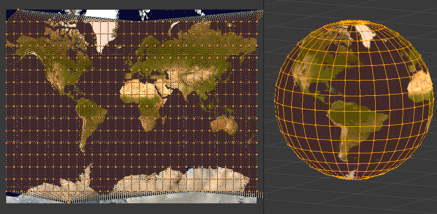
Using a Mercator image with a Sphere Projection.
Cylindrical and Spherical mappings have the same settings. The difference is that a cylindrical mapping projects the UVs on a plan toward the cylinder shape, while a spherical map takes into account the sphere’s curvature, and each latitude line becomes evenly spaced.
Normally, to unwrap a cylinder (tube) as if you slit it lengthwise and folded it flat, Blender wants the view to be vertical, with the tube standing “up”. Different views will project the tube onto the UV map differently, skewing the image if used. However, you can set the axis on which the calculation is done manually. This same idea works for the sphere mapping:
Recall the opening cartographer’s approaching to mapping the world? Well, you can achieve the same here when unwrapping a sphere from different perspectives. Normally, to unwrap a sphere, view the sphere with the poles at the top and bottom. After unwrapping, Blender will give you a Mercator projection; the point at the equator facing you will be in the middle of the image. A polar view will give a very different but common projection map. Using a Mercator projection map of the earth as the UV image will give a very nice planet mapping onto the sphere.
Operator panel
- Direction
- View on Poles
- Use when viewing from the top (at a pole) by using an axis that is straight down from the view.
- View on Equator
- Use if view is looking at the equator, by using a vertical axis.
- Align to Object
- Uses the object’s transform to calculate the axis.
- Align
Select which axis is up.
- Polar ZX
- Polar 0 is on the X axis.
- Polar ZY
- Polar 0 is on the Y axis.
- Radius
- The radius of the cylinder to use.
Project From View
In the 3D View, the option maps the face as seen through the view of the 3D View it was selected from. It is almost like you had x-ray vision or squashed the mesh flat as a pancake onto the UV map. Use this option if you are using a picture of a real object as a UV Texture for an object that you have modeled. You will get some stretching in areas where the model recedes away from you.
Project From View (Bounds)
Using Project from View (Bounds) will do the same as above, but scales the UVs to the bounds of the UV space.
Reset
In the 3D View, maps each selected face to the same area of the image, as previously discussed. To map all the faces of an object (a cube, for example) to the same image, select all the faces of the cube, and unwrap them using the Reset menu option.