Object Data
Reference
Cameras are invisible in renders, so they do not have any material or texture settings. However, they do have Object and Editing setting panels available which are displayed when a camera is the selected (active!) object.
Lens
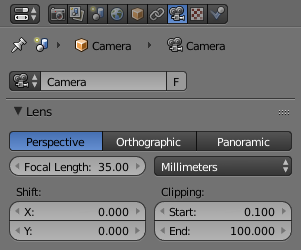
Camera Lens panel.
The camera lens options control the way 3D objects are represented in a 2D image.
Lens Type
There are three different lens types:
Perspective
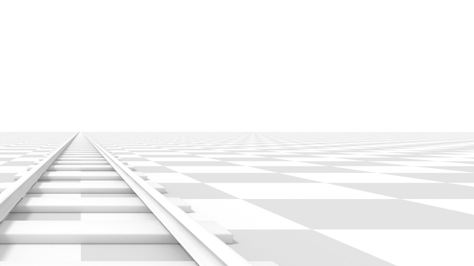
This matches how you view things in the real-world. Objects in the distance will appear smaller than objects in the foreground, and parallel lines (such as the rails on a railroad) will appear to converge as they get farther away.
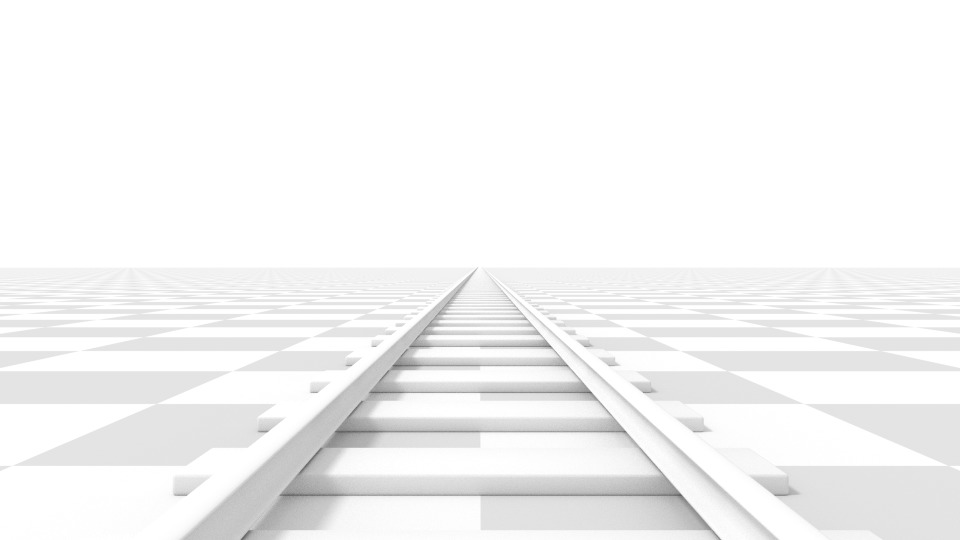
Render of a train track scene with a Perspective camera.
Settings which adjust this projection include:
- Focal length
- Shift
- Sensor size
- Focal length
The focal length setting controls the amount of zoom, i.e. the amount of the scene which is visible all at once. Longer focal lengths result in a smaller FOV (more zoom), while short focal lengths allow you to see more of the scene at once (larger FOV, less zoom).
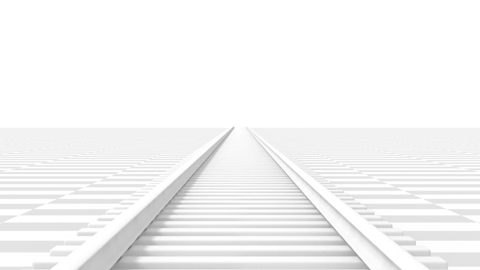
Render of the same scene as above, but with a focal length of 210mm instead of 35mm.
- Lens Unit
- The focal length can be set either in terms of millimeters or the actual Field of View as an angle.
Orthographic
With Orthographic perspective objects always appear at their actual size, regardless of distance. This means that parallel lines appear parallel, and do not converge like they do with Perspective.
Render from the same camera angle as the previous examples, but with orthographic perspective.
- Orthographic Scale
This controls the apparent size of objects in the camera.
Note that this is effectively the only setting which applies to orthographic perspective. Since parallel lines do not converge in orthographic mode (no vanishing points), the lens shift settings are equivalent to translating the camera in the 3D View.
Panoramic
Panoramic cameras are only supported in the Cycles render engine. See the Cycles documentation.
Shift
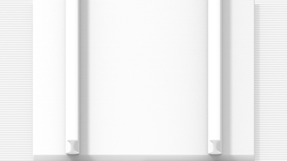
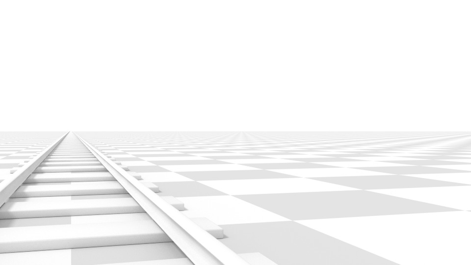
The Shift setting allows for the adjustment of vanishing points. Vanishing points refer to the positions to which parallel lines converge. In this example, the most obvious vanishing point is at the end of the railroad.
To see how this works, take the following examples:
Render of a train track scene with a horizontal lens shift of 0.330.
Render of a train track scene with a rotation of the camera object instead of a lens shift.
Notice how the horizontal lines remain perfectly horizontal when using the lens shift, but do get skewed when rotating the camera object.
Using lens shift is equivalent to rendering an image with a larger FOV and cropping it off-center.
Clipping
- Clip Start and End
- The interval in which objects are directly visible; Only objects within the limits are rendered.
For OpenGL display, setting clipping distances to limited values is important to ensure sufficient rasterization precision. Ray tracing renders do not suffer from this issue so much, and as such more extreme values can safely be set.
When Limits in the Display panel is enabled, the clip bounds will be visible as two yellow connected dots on the camera line of sight.
Tip
Changing the clipping value can have a serious impact on render performance. It is important to always set the Start and End values to a safe distance that is both not too extreme, nor too small to have the best possible render times.
See also
Camera
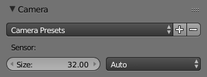
Camera Presets panel.
- Camera Presets
- Presets to match real cameras.
- Sensor size
- This setting is an alternative way to control the focal-length, it is useful to match the camera in Blender to a physical camera & lens combination, e.g. for motion tracking.
- Sensor Fit
- Option to control which dimension (vertical or horizontal) along which field of view angle fits.
Depth of Field
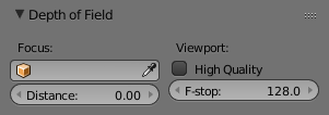
Camera Depth of Field Panel.
Real world cameras transmit light through a lens that bends and focuses it onto the sensor. Because of this, objects that are a certain distance away are in focus, but objects in front and behind that are blurred.
The area in focus is called the focal point and can be set using either an exact value, or by using the distance between the camera and a chosen object:
- Focus Object
- Choose an object which will determine the focal point. Linking an object will deactivate the distance parameter. Typically this is used to give precise control over the position of the focal point, and also allows it to be animated or constrained to another object.
- Distance
Sets the distance to the focal point when no Focus Object is specified. If Limits are enabled, a yellow cross is shown on the camera line of sight at this distance.
Hint
Hover the mouse over the Distance property and press
Eto use a special Depth Picker. Then click on a point in the 3D View to sample the distance from that point to the camera.- High Quality
- In order for the viewport to offer an accurate representation of depth of field (blur radius calculation), like a render, you must enable High Quality. Without it, you may notice a difference in shading. (Grayed out if not supported by the GPU).
- Viewport F-stop
- Controls the real-time focal blur effect used during sequencer or OpenGL rendering and, when enabled, camera views in the 3D View. The amount of blur depends on this setting, along with Focal Length and Sensor Size. Smaller Viewport F-stop values result in more blur.
- Blades
- Add a number of polygonal blades to the blur effect, in order to achieve a a bokeh effect in the viewport. To enable this feature, the blades must be set to at least 3 (3 sides, triangle)
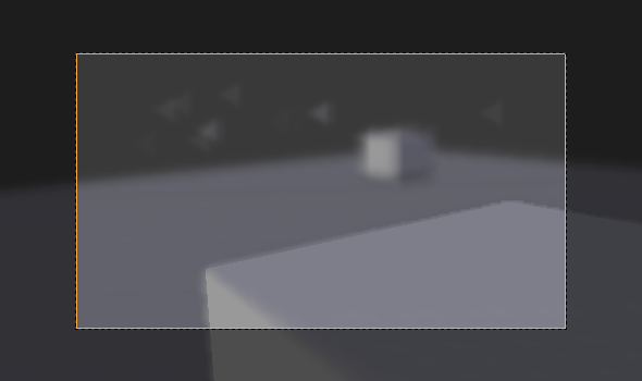
The viewport bokeh effect with the blades set to 3.
Display
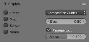
Camera Display Panel.
- Limits
- Shows a line which indicates Start and End Clipping values.
- Mist
- Toggles viewing of the mist limits on and off. The limits are shown as two connected white dots on the camera line of sight. The mist limits and other options are set in the World panel, in the Mist section.
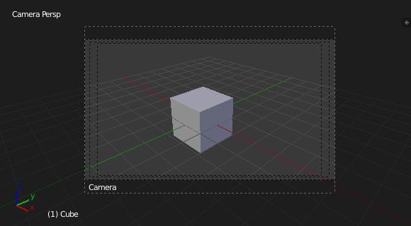
Camera view displaying safe areas, sensor and name.
- Sensor
- Displays a dotted frame in camera view.
- Name
- Toggle name display on and off in camera view.
- Size
- Size of the camera icon in the 3D View. This setting has no effect on the render output of a camera,
and is only a cosmetic setting.
The camera icon can also be scaled using the standard Scale
Stransform key. - Passepartout
This option darkens the area outside of the camera’s field of view.
- Alpha
- Controls the transparency of the passepartout mask.
Composition Guides
Composition Guides are available from the menu, which can help when framing a shot. There are eight types of guides available:
- Center
- Adds lines dividing the frame in half vertically and horizontally.
- Center Diagonal
- Adds lines connecting opposite corners.
- Thirds
- Adds lines dividing the frame in thirds vertically and horizontally.
- Golden
- Divides the width and height into Golden proportions (About 0.618 of the size from all sides of the frame).
- Golden Triangle A
- Draws a diagonal line from the lower-left to upper-right corners, then adds perpendicular lines that pass through the top left and bottom right corners.
- Golden Triangle B
- Same as A, but with the opposite corners.
- Harmonious Triangle A
- Draws a diagonal line from the lower-left to upper-right corners, then lines from the top left and bottom right corners to 0.618 the lengths of the opposite side.
- Harmonious Triangle B
- Same as A, but with the opposite corners.
Safe Areas
Safe areas are guides used to position elements to ensure that the most important parts of the content can be seen across all screens.
Different screens have varying amounts of overscan. (specially older TV sets). That means that not all content will be visible to all viewers, since parts of the image surrounding the edges are not shown. To work around this problem TV producers defined two areas where content is guaranteed to be shown: action safe and title safe.
Modern LCD/plasma screens with purely digital signals have no overscan, yet safe areas are still considered best practice and may be legally required for broadcast.
In Blender, safe areas can be set from the Camera and Sequencer views.
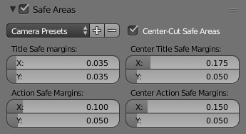
The Safe areas panel found in the camera properties, and the view mode of the sequencer.
The Safe Areas can be customized by their outer margin, which is a percentage scale of the area between the center and the render size. Values are shared between the Video Sequence editor and camera view.
Main Safe Areas
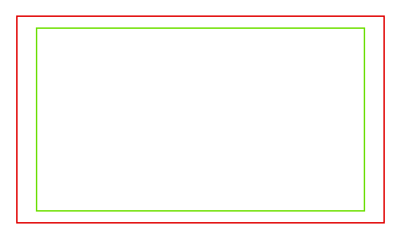
Red line: Action safe. Green line: Title safe.
- Title Safe
- Also known as Graphics Safe. Place all important information (graphics or text) inside this area to ensure it can be seen by the majority of viewers.
- Action Safe
- Make sure any significant action or characters in the shot are inside this area. This zone also doubles as a sort of “margin” for the screen which can be used to keep elements from piling up against the edges.
Tip
Legal Standards
Each country sets a legal standard for broadcasting. These include, among other things, specific values for safe areas. Blender defaults for safe areas follow the EBU (European Union) standard. Make sure you are using the correct values when working for broadcast to avoid any trouble.
Center-Cuts
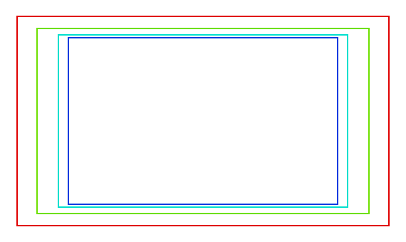
Cyan line: action center safe. Blue line: title center safe.
Center-cuts are a second set of safe areas to ensure content
is seen correctly on screens with a different aspect ratio.
Old TV sets receiving 16:9 or 21:9 video will cut off the sides.
Position content inside the center-cut areas to make sure the most important elements
of your composition can still be visible in these screens.
Blender defaults show a 4:3 (square) ratio inside 16:9 (wide-screen).