Shear
Reference
Shift-Ctrl-Alt-SShearing is a form of movement where parallel surfaces move past one another. During this transform, movement of the selected elements will occur along the horizontal axis of the current view. The axis location will be defined by the Pivot Point. Everything that is “above” this axis will move (Shear) in the same direction as your mouse pointer (but always parallel to the horizontal axis). Everything that is “below” the horizontal axis will move in the opposite direction.
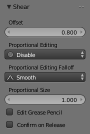
Shear Offset Factor.
Usage
Select the elements you want to operate on and activate the Shear transform
function. The Shear option can be invoked from the
menu option or by pressing
Shift-Ctrl-Alt-S. The amount of movement given to the selection can be determined
interactively by moving the mouse or by typing a number.
Pressing Return will confirm the transformation. The confirmed transformation can
be further edited by pressing F6 or by going into the Tool Shelf and altering
the Offset slider provided that no other actions take place between the Shear
transform confirmation and accessing the slider.
Note that the result of the Shear transform is also dependant on the number and type of selected elements (Objects, vertices, faces etc). See below for the result of using Shear on a number of different elements.
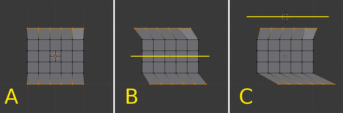
The effects of a Shear transform with different Pivot Points. See the text below for additional information.
The three frames of the image above show the effects of shearing on the selected vertices when the pivot point is altered. In frame B, the Pivot Point is set to Median Point (indicated by the yellow line) and the mouse was moved to the left during the transform. In frame C, the Pivot Point is set to the 3D cursor which is located above the mesh (indicated again by the yellow line). When the mouse is moved to the left during a Shear transform the selected vertices are moved to the right as they are below the horizontal axis.
Tip
Shear transform magnitude
The magnitude of the Shear transform applied to the selected elements is directly proportional to the distance from the horizontal axis. i.e. the further from the axis, the greater the movement.
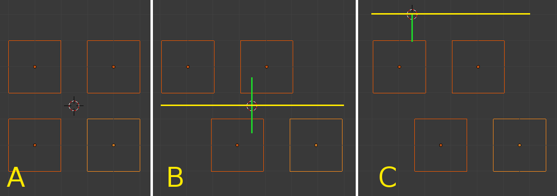
The effects of a Shear transform on Objects with different Pivot Points. See the text below for additional information.
The three frames of the image above show the effects of shearing on the selected Objects when the Pivot Point is altered. In frame B, the Pivot Point is set to Median Point (indicated by the yellow line) and the mouse was moved to the left during the transform. In frame C, the Pivot Point is set to the 3D cursor which is located above the Objects (indicated again by the yellow line). When the mouse is moved to the left during a Shear transform all of the selected Objects are moved to the right as they are below the horizontal axis. Again, note that the magnitude of the transform is proportional to the distance from the horizontal axis. In this case, the lower Objects move further than the upper ones.