Geometry Node
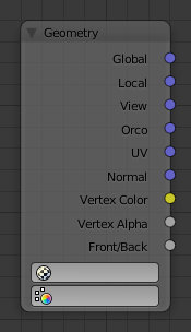
Geometry node.
The geometry node is used to specify how light reflects off the surface. This node is used to change a material’s Normal response to lighting conditions.
Use this node to feed the Normal vector input on the Material node, to see how the material will look (e.g. shine, or reflect light) under different lighting conditions. Your choices are:
Inputs
This node has no inputs.
Properties
- UV Map
- To select a listed UV map.
- Color Layer
- To select a listed vertex color data (Vertex Paint, Weight Paint).
Outputs
- Global
- Global position of the surface.
- Local
- Local position of the surface.
- View
- Viewed position of the surface.
- Orco
- Using the Original Coordinates of the mesh.
- UV
- Using the UV coordinates of the mesh, selected in the field in bottom node.
- Normal
- Surface Normal; On a flat plane with one light above and to the right reflecting off the surface.
- Vertex Color
- Allows for output value of group vertex colors, selected in the field in bottom node.
- Vertex Alpha
- Allows for output alpha value of vertex.
- Front/Back
- Allows for output to take into account front or back of surface is light relative the camera.
Note
These are exactly the same settings as in the Mapping panel for Textures, though a few settings, like Stress or Tangent, are missing here. Normally you would use this node as input for a Texture Node.
Geometry Node Example using a UV image
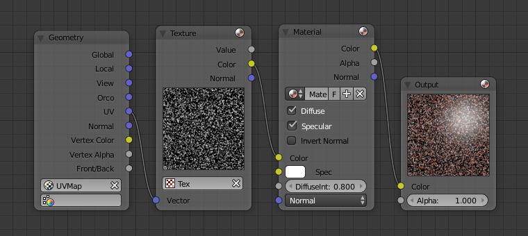
Setup to render a UV-Mapped Image Texture.
E.g.: To render a UV-mapped image, you would use the UV output and plug it into the Vector Input of a texture node. Then you plug the color output of the texture node into the color input of the material node, which corresponds to the setting on the Map To panel.