Workflow
The process consists of the following steps:
- Create the Mesh. Unwrap it into one or more UV Layouts.
- Create one or more Materials for the Mesh.
- Create one or more images for each UV Layout and aspect of the texture. Either - Paint directly on the mesh using Texture Paint in the 3D View, - Load and/or edit an image in the UV/Image Editor, or - Bake the existing materials into an image for the UV/Image Editor.
- Apply those images as UV Textures to the mesh to affect one or more aspects of the mesh. This is done by using one or more of the numerous Map To options. For example, - Map to Color to affect the diffuse coloring of the mesh, - Map to Nor to affect the normal direction to give the surface a bumpy or creased look, or - Map to Spec (specularity) to make certain areas look shiny and oily.
- Layer the Textures to create a convincing result.
Using Images and Materials
To use an image as the color and alpha (transparency) of the texture, you can create an image in an external paint program and tell the UV/Image Editor to Open that file as the texture, or you can create a New image and save it as the texture.
If you want to start off by creating an image using an external paint program, you will want to save an outline of your UV faces by using the Save UV Face Layout tool located in the UVs menu. This is discussed here.
Creating an Image Texture
To create an image within Blender, you have to first create a New Blank Image with a uniform color or test grid. After that, you can color the image using the:
- Vertex colors as the basis for an image.
- Render Bake image based on how the mesh looks in the scene.
After you have created your image, you can modify it using Blender’s built-in Texture Paint or any external image painting program.
Note
See Texture in 3D View but does not Render
You may be able to see the texture in Textured display mode in the 3D View; this is all that is required to have textures show up in Blender’s Game Engine. Rendering, however, requires a material. You must have a Face Textures material assigned to the mesh for it to render using the UV Texture. In the Material settings, Add New material to a selected object and enable Face Textures.
Examples
There may be one UV Layout for the face of a character, and another for their clothes. Now, to texture the clothes, you need to create an image at least for the Color of the clothes, and possible a “bump” texture to give the fabric the appearance of some weave by creating a different image for the Normal of the clothes. Where the fabric is worn, for example at the elbows and knees, the sheen, or Specularity, of the fabric will vary and you will want a different image that tells Blender how to vary the Specularity. Where the fabric is folded over or creased, you want another image that maps Displacement to the mesh to physically deform the mesh. Each of these are examples of applying an image as a texture to the mesh.
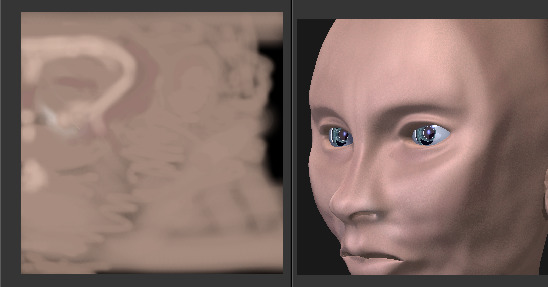
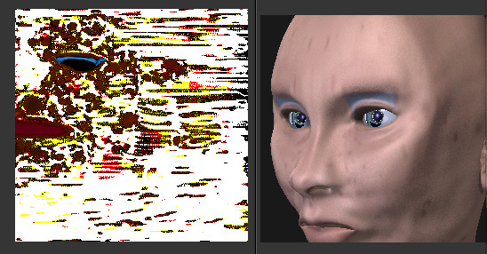
As another example, the face is the subject of many questions and tutorials. In general, you will want to create a Material that has the basic skin color, appropriate shaders, and sub-surface scattering. Then you will want to layer on additional UV Textures for:
- Freckle map for Color and Normal aspects.
- Subdermal veins and tendons for Displacement.
- Creases and Wrinkles and skin cell stratification for Normal.
- Makeup images for Color.
- Oily maps for Specularity.
- For a zombie, Alpha transparency where the flesh has rotted away.
- Under chin and inside nostrils that receive less Ambient light.
- Thin skin is more translucent, so a map is needed for that.
Each image is mapped by using another Texture Channel. Each of these maps are images which are applied to the different aspects (Color, Normal, Specularity) of the image. Tileable images can be repeated to give a smaller, denser pattern by using the Texture controls for repeat or size.
Layering UV Textures
Base UV Texture. |
Layered UV Texture. |
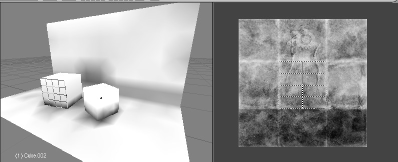
Great textures are formed by layering images on top of one another. You start with a base layer, which is the base paint. Each successive layer on top of that is somewhat transparent to let the bottom layers show through, but opaque where you want to add on to details.
To avoid massive confusion, all image textures for a mesh usually use the same UV map. If you do, each image will line up with the one below it, and they will layer on top of one another like the examples shown to the right. To do this, just create one UV Texture (map) as described in this section. Then, create material image textures as described in the procedural materials section. Instead of mapping to Original Coordinates (OrCo), map to UV.
Use that map name repeatedly in the panel by selecting UV and typing the name in the text field. In the example to the right, our UV Texture is called “Head” (you may have to expand the image to see the panel settings). Then, the image texture shown will be mapped using the UV coordinates. In the “Base UV Texture” example to the right, the face has two textures UV mapped; one for a base color, and another for spots, blemishes and makeup.
Both textures use the same UV Texture map as their Map Input, and both affect Color. The Makeup texture is transparent except where there is color, so that the base color texture shows through. Note that the colors were too strong on the image, so they amount of the diffuse color affects is turned down to 60% in the second layer (the blemish layer).
Normally, we think of image textures affecting the color of a mesh. Realism and photo-realistic rendering is a combination of many different ways that light interacts with the surface of the mesh. The image texture can be Mapped To not only color, but also Normal (bumpiness) or Reflection or any of the other attributes specified in the Map To panel.
If you paint a gray-scale image (laid out according to the UV Layout) with white where the skin is oily and shiny, and dark where it is not, you would map that input image according to the UV Layout, but have it affect Specularity (not color).
To make portions of a mesh transparent and thus reveal another mesh surface underneath, you would paint a gray-scale image with black where you want the texture transparent, map input to UV, and map it to Alpha (not color). To make portions of a mesh, like a piece of hot metal, appear to glow, you would use a gray-scale image mapped to Emit.
Believe it or not, this is only “the tip of the iceberg!” If everything that is been described here just is not enough for you, the texture nodes feature, introduced in recent versions of Blender, enables you to layer and combine textures in almost any way you can imagine.
Mix and Match Materials
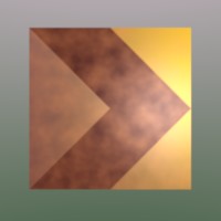
You can mix and match procedural materials and textures, vertex paint, and UV textures onto the same mesh.
The image to the right has a world with a red ambient light. The material has both Vertex Color Paint and Face Textures enabled, and receives half of ambient light. A weak cloud texture affects color, mixing in a tan color. The right vertices are vertex painted yellow and the left is unpainted procedural gray. The UV Texture is a stock arrow image from the public domain texture CD. Scene lighting is a white light off to the right. From this information and the User Manual thus far, you should now be able to recreate this image.
You can also assign multiple materials to the mesh based on which faces you want to be procedural and which you want to be texture-mapped. Just do not UV map the faces you want to be procedural.
You can use UV Textures and Vertex Paint (V in the 3D View) simultaneously,
if both are enabled in the Material settings.
The vertex colors are used to modulate the brightness or color of the UV image texture:
- UV Texture is at the base (Face Textures)
- Vertex paint affects its colors, then
- Procedural textures are laid on top of that,
- Area lights shine on the surface, casting shadows and what not, and finally
- Ambient light lights it up.
Vertex colors modulate texture.
A UV Layout can only have one image, although you can tile and animate the image. Since a layout is a bunch of arranged UV Maps, and a UV Map maps many mesh faces, a face can therefore only have one UV Texture image, and the UV coordinates for that face must fit entirely on the image. If you want a face to have multiple images, split the face into parts, and assign each part its own image. (Or you can get fancy with Nodes, but that is another story ...)
Using Alpha Transparency
Alpha UV Textures.
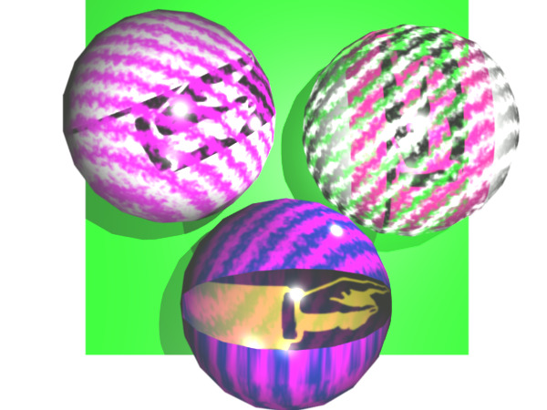
Alpha 0.0 (transparent) areas of a UV Image render as black. Unlike a procedural texture, they do not make the base material transparent, since UV Textures do not operate on the base procedural material. The UV texture overrides any procedural color underneath. Procedural Textures are applied on top of UV Textures, so a procedural image texture would override any UV Texture. Transparent (black) areas of a procedural texture mapped to alpha operate on top of anything else, making the object transparent in those places. The only thing that modulates visible parts of a UV Texture are the Vertex Colors. In the example to the right, the finger image is transparent at the cuff and top of the finger and is used as a UV Texture. All three balls have a base material of blue and a marbling texture. The base material color is not used whenever Face Textures is enabled.
The top left ball has not had any vertex painting, and the finger is mapped to the middle band, and the texture is mapped to a pink color. As you can see, the base material has Vertex Color Paint and Face Textures enabled; the base color blue is not used, but the texture is. With no vertex painting, there is nothing to modulate the UV Texture colors, so the finger shows as white. Transparent areas of the UV Image show as black.
The top right ball has had a pink vertex color applied to the vertical band of faces (in the 3D View editor, select the faces in UV Paint Mode, switch to Vertex Paint Mode, pick a pink color, and ). The finger is mapped to the middle vertical band of faces, and Vertex Color and Face Textures are enabled. The texture is mapped to Alpha black and multiplies the base material alpha value which is 1.0. Thus, white areas of the texture are 1.0, and 1.0 times 1.0 is 1.0 so that area is opaque and shows. Black areas of the procedural texture, 0.0, multiply the base material to be transparent. As you can see, the unmapped faces (left and right sides of the ball) show the vertex paint (none, which is gray) and the painted ones show pink, and the middle stripe that is both painted and mapped change the white UV Texture areas to pink. Where the procedural texture says to make the object transparent, the green background shows through. Transparent areas of the UV Texture insist on rendering black.
The bottom ball uses multiple materials. Most of the ball (all faces except the middle band) is a base material that does not have Face Textures (nor Vertex Color Paint) enabled. Without it enabled, the base blue material color shows and the pink color texture is mixed on top. The middle band is assigned a new material (2 Mat 2) that does have vertex paint and Face Textures enabled. The middle band of faces were vertex painted yellow, so the white parts of the finger are yellow. Where the pink texture runs over the UV texture, the mixed color changes to green, since pink and yellow make a green.
If you want the two images to show through one another, and mix together, you need to use Alpha. The base material can have an image texture with an Alpha setting, allowing the underlying UV Texture to show through.
To overlay multiple UV images, you have several options:
- Create multiple UV Textures which map the same, and then use different images (with Alpha) and Blender will overlay them automatically.
- Use the Composite Nodes to combine the two images via the Alpha Over node, creating and saving the composite image. Open that composited image as the UV Texture.
- Use an external paint program to alpha overlay the images and save the file, and load it as the face’s UV Texture
- Define two objects, one just inside the other. The inner object would have the base image, and the outer image the overlaid image with a material alpha less than one (1.0).
- Use the Material nodes to combine the two images via the Alpha Over or Mix node, thus creating a third noded material that you use as the material for the face. Using this approach, you will not have to UV map; simply assign the material to the face using the Multiple Materials.